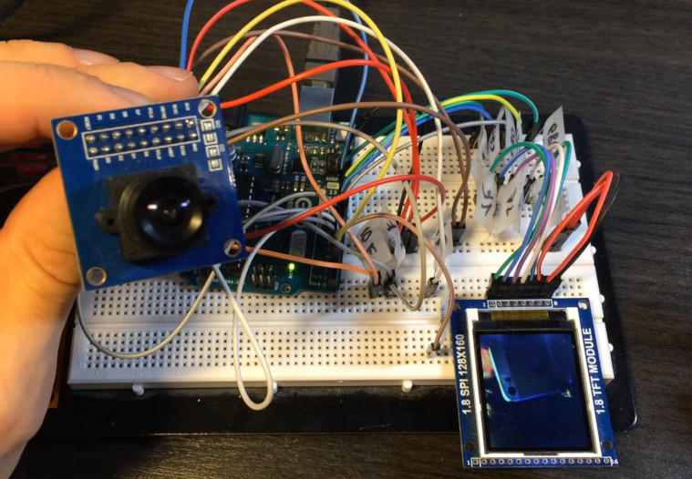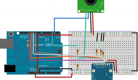


The Arduino is powerful enough to do more sophisticated image processing. What if you want to find the darkest area in an image instead of the brightest? That’s easy - just invert the captured image before processing it. Enable external interrupt INT0 on pin 2 with falling edge.ĪDCSRB |= _BV(ACME) // enable ADC multiplexerĪDMUX &= ~_BV(MUX0) // select A2 for use as AIN1 (negative voltage of comparator)ĪCSR &= ~_BV(ACIE) // disable analog comparator interruptsĪCSR &= ~_BV(ACIC) // disable analog comparator input capture ICES0 is set to 0 for falling edge detection on input capture pin. If you use a television with the PAL standard (that is, you are not in North America), change tv.begin(NTSC, W, H) to tv.begin(PAL, W, H). If you have a robot with a camera on it, you can detect/track objects with Arduino code, and the output of the Video Experimenter doesn’t need to be connected to anything (although the analog threshold potentiometer would probably need some adjustment). Keep in mind that there is no need to display any output at all - we just do this so we can see what’s going on.

Finally, tv.resume() is called to resume the output and display the box and coordinates on the screen. After computing the location of the brightest area, a box is drawn and the coordinates of the box are printed to the TVout frame buffer.

Then it computes a simple bounding box for the brightest spot in the image.
#Arduino camera image processing code
The code first calls tv.capture() to capture a frame. This project is the example “ObjectTracking” in the TVout library for Video Experimenter. Here is an Arduino sketch that captures a video frame and then computes the bounding box of the brightest region in the image. Set the analog threshold potentiometer to the lowest setting. The output select switch is set to “overlay”, and sync select jumper set to “video input”. The setup is the same as when capturing video frames: a video source like a camera is connected to the video input. We can take this concept further by processing the contents of the captured image to implement object tracking and edge detection.
#Arduino camera image processing how to
In the Video Frame Capture project, I showed how to capture images from a composite video source and display them on a TV. The Video Experimenter shield can give your Arduino the gift of sight.


 0 kommentar(er)
